Welcome to Day 7: The Master Synthesis.
We’ve spent the last six days tearing apart the physics of stiffness—from the atomic bonds of steel to the microscopic squish of bolted joints. Today, we pull it all together into a highly actionable engineering playbook.
We will learn how to build a "Stiffness Budget," lay out the 12 Iron Rules of structural design, and finally, learn how to physically prove that your computer simulation wasn't lying to you.
I. The Stiffness Budget: Working Backwards from Perfection
1.1 What is a Stiffness Budget?
In precision engineering, an "Error Budget" is the master document. You start with the absolute maximum error your machine is allowed to make (say, 1 micrometer), and you divvy up that error among all your subsystems: thermal expansion, geometric flaws, servo lag, and structural bending.
A Stiffness Budget is the mechanical execution of that document: Working backward from the allowed precision error to dictate exactly how much "flex" is legally permitted in every single chunk of metal.
Generally, geometric manufacturing errors are the largest source of raw error, but they can be mathematically compensated for by the software. Thermal drift is the largest error left over after compensation. Structural deformation (stiffness) usually eats up 15% to 25% of your total error budget.
1.2 The Six-Step Budgeting Process
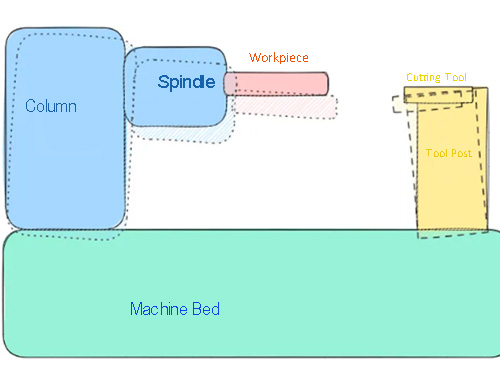
(1)Identify the Death Axis: Which direction of movement ruins the product? For a lathe, it's the line between the cutting tool tip and the workpiece. For a lithography machine, it's the Z-axis (focus) and XY-axis (overlay).
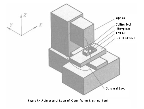
(2)Map the Force River: Draw the exact path the force takes from where it is applied down to the solid ground. Identify every single component, bolted joint, bearing, and guide rail sitting in that series chain. If you do this right, you’ve already won half the battle.
(3)Estimate the Flex: Calculate the flexibility of the solid beams using standard formulas. Estimate joint flexibility using Rivin's data or VDI 2230. Check bearing catalogs for their stiffness specs.
(4)Find the Bottleneck: Remember the rule of series springs (1/ktotal≈1/kmin). Find the softest, weakest link in your chain. That is your biggest risk.
(5)Divvy up the Budget: Assign stiffness quotas. A typical breakdown looks like this:
a.Main Frame/Bed: Must consume ≤20%-30% of total flex.
b.Guide Rails & Bearings: Will consume ≤30%-40% (moving interfaces are naturally squishy).
c.Bolted Joints: Each joint ≤5%-10%.
d.The Rule of Thumb: If your main structural frame is eating up more than 50% of your allowed flex, your design is doomed. Bearings and joints are naturally flexible; you must rely on massive, stiff frames to carry the load.
(6)Iterate: Estimate → Find the weak link → Beef it up → Re-calculate. It usually takes 2 to 3 rounds of this to hit your target.
II. The 12 Iron Rules of Precision Design
Synthesized from the legendary works of Rivin, Slocum, Blanding, and Hale.
Macro-Topology
Rule 1: Keep the chain short. Every link in a series path adds flexibility. Always prioritize direct connections over multi-part assemblies.
Rule 2: Forces love straight lines. When a force turns a corner, it creates a bending moment. Remember, bending stiffness is 100 to 1,000 times weaker than axial (push/pull) stiffness. Never bend if you can push.
Rule 3: Beware the Open-Section Chasm. Under twisting loads, closed-box shapes are 100 to 1,000 times stiffer than open shapes (like I-beams). The default shape for any precision frame must be a closed box or a tube.
Rule 4: Gantry > C-Frame (If you have the space). Supporting a beam on both ends reduces bending by 16 to 64 times compared to a cantilevered C-frame. But remember, smaller machines prioritize operator access, so C-frames still dominate there.
Geometry
Rule 5: Height is the Master Key. Bending stiffness scales with height cubed (h3) for rectangles and diameter to the fourth power (D4) for tubes. Push material as far away from the center axis as possible.
Rule 6: Hollow is Magic. A thin-walled tube retains roughly 60% of the stiffness of a solid rod but sheds nearly 65% of the weight. Hollow structures aren't just for weight savings; they are the peak of structural efficiency.
Rule 7: Rib Depth > Rib Thickness. Deep, thin ribs add vastly more stiffness than shallow, thick ones (until you hit buckling limits). Ensure ribs are perpendicular to the direction of the bending force.
Contact Interfaces
Rule 8: Kill the Joints. Every bolted joint is a squishy spring. If you can use 3D printing or complex casting to make a monolithic frame and eliminate bolts, do it.
Rule 9: Preload is your Shield. Contact stiffness grows with clamping pressure. Torque your bolts as high as safely possible. Under-tightening causes catastrophic stiffness collapse long before the bolt ever vibrates loose.
Dynamics
Rule 10: The 3x Rule. The machine's first natural frequency (fn,1) must be at least 3 times higher than the highest frequency of your servo motor system. If you can't hit that, drop weight first, then add stiffness.
Rule 11: Point the shake away. You can never eliminate all resonance. But you can design the structure so that when it does shake, the mode shape vibrates in a direction that your sensors don't care about.
Materials
Rule 12: Respect the Heat. If your machine generates heat, watch out for dE/dT (stiffness dropping as heat rises) and CTE (thermal expansion). Long structures + high CTE + rigid bolting = thermal stress disasters.
III. Proving It: Testing Your Math
3.1 Static Stiffness Testing
The method is brutal and honest: Apply a force → Measure the displacement → Calculate k=F/δ.
The Golden Rule: The sensor measuring the displacement must be mounted on a completely separate, independent frame from the hydraulic ram applying the force. If they share a frame, the sensor will read the flexing of the loading tool, making your machine look much softer than it really is.
3.2 Experimental Modal Analysis (EMA)
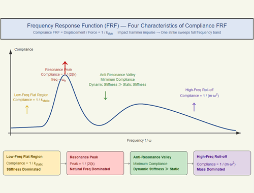
Hit the machine with an Impact Hammer → Measure the ringing with Accelerometers → Run it through a Fast Fourier Transform (FFT) → Get your frequency peaks.
EMA gives you three things software (FEA) never will:
True Natural Frequencies: Software assumes your machine is bolted to an infinitely stiff floor. EMA measures reality.
True Damping Ratios: Software asks you to guess the damping. EMA measures it perfectly.
The Lie Detector: If your FEA frequency differs from your EMA frequency by more than 10%, your computer model is lying to you (usually because you modeled the bolted joints incorrectly).
3.3 Why FEA Fails
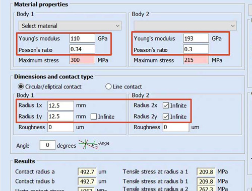
The "Bonded" Trap: The biggest mistake engineers make is setting contact surfaces as "bonded" (infinitely stiff) in software. Real bolted joints are 2 to 3 times softer than this.
Fake Rigid Ground: Software assumes the floor never moves. Real concrete floors and leveling feet flex.
Assembly Stress: Software assumes perfect, stress-free assembly. In reality, torquing bolts out of order warps the metal, changing the physical path of the forces.
IV. The Dual-Core Engine of Precision Design
Precision design requires mastering two distinct disciplines: Exact Constraint Design (managing Degrees of Freedom, which we will cover in a future series) and Stiffness Design (managing forces and flex, which we just finished).
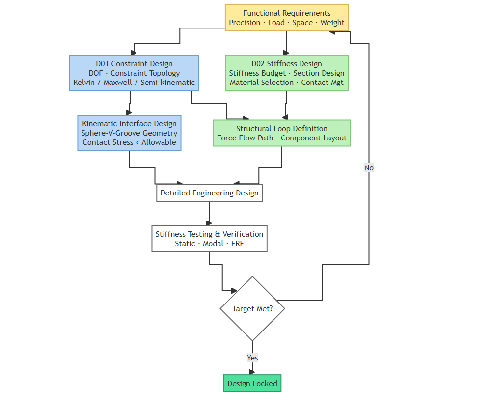
They meet at the Kinematic Interface. Constraint rules dictate where a ball sits in a V-groove. Stiffness rules dictate the radius of that ball and how hard it is pressed down. Violate constraint rules, and you generate massive thermal and assembly stresses. Violate stiffness rules, and your machine shakes itself apart.
V. The 7 Deadly Sins (A Recap)
If you only remember seven things from this week, let it be these:
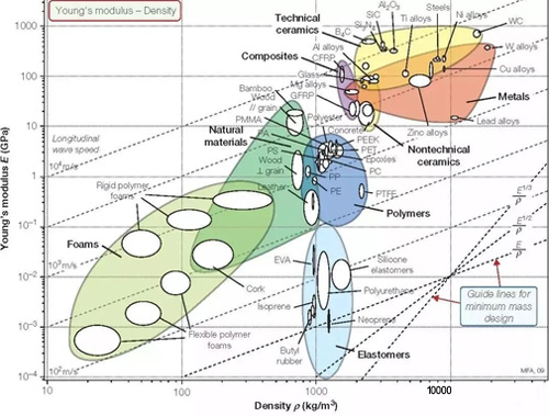
Confusing Material with Structure: Steel's E is 3x higher than aluminum. That does not mean your steel frame will be 3x stiffer. Geometry’s leverage always beats material.
The "High-Strength" Fallacy: Heat-treating steel makes it stronger, but its Elastic Modulus (E) stays exactly the same. You cannot heat-treat your way to higher stiffness.
The FEA Bonded Lie: Setting joints to "bonded" in FEA guarantees your machine will be vastly softer in reality than on screen.
Ignoring the Weak Link: Spending $10,000 to stiffen a massive steel frame is useless if you bolt it to the floor with a flimsy, soft bracket.
Only Calculating Static Stiffness: It doesn't matter how stiff a machine is when it's turned off. If its natural frequency matches your motor speed, the dynamic vibrations will be 50 times larger than the static flex.
The Carbon Fiber Trap: It has amazing theoretical stiffness, but its inability to be welded, its weakness across the grain, and its tendency to swell with humidity often make it perform worse than cheap aluminum extrusions in factory environments.
Forgetting Damping: At resonance, dynamic stiffness is entirely controlled by damping (2ζk). Cast iron has 5x the damping of steel. It will survive resonance vibrations 5x better.
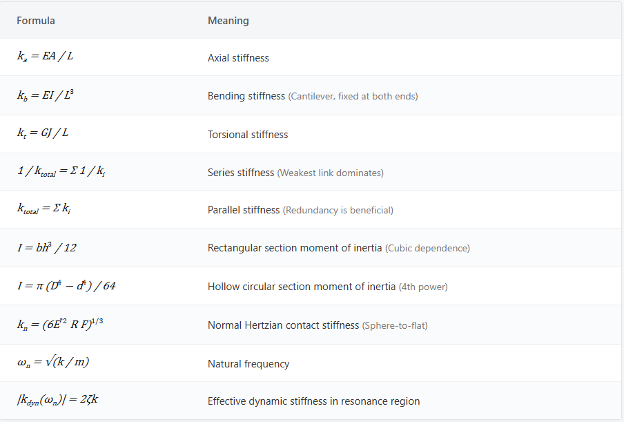
Quick Reference: This Week's Core Formulas
VI. What's Next? The Silence of Damping
Stiffness tells you how much a machine bends when you push it. But stiffness cannot answer one crucial question: How do we make the shaking stop?
If you build a cast iron machine and a welded steel machine with the exact same stiffness and the exact same natural frequency, the cast iron machine will stop vibrating 5 to 10 times faster.
Why? Damping.
References
[1]Rivin, E. I., Stiffness and Damping in Mechanical Design, Marcel Dekker, 1999, Ch.6 "Design for Stiffness". (The complete engineering guide for stiffness budgeting, design rules, and experimental methods.) Note: This article is adapted from the WeChat public account "Mechanical Architect", edited for educational exchange. Copyright belongs to the original creator.
[2] VDI 2230 Part 1, Systematic Calculation of Highly Stressed Bolted Joints, 2015. (The industrial standard for calculating bolted joint flexibility.)
[3] Slocum, A. H., Precision Machine Design, SME, 1992, §6.7 "Design Case Studies". (Machine tool bed design case studies, including structural loop analysis.)
[4] Blanding, D. L., Exact Constraint: Machine Design Using Kinematic Processing, ASME Press, 1999, §1.1–1.3. (The fundamental principles of exact constraint design.)
[5] Hale, L. C., Principles and Techniques for Designing Precision Machines, PhD Thesis, MIT, 1999, Ch.7 "Design Methodology". (A complete workflow for precision machine design, integrating constraints and stiffness.)
[6] Inman, D. J., Engineering Vibration, 4th ed., Pearson, 2014, Ch.7 "Experimental Modal Analysis". (Standard methods for experimental modal analysis—impact hammer, accelerometers, FRF processing.)