Welcome to Day 5: The Dynamics.
Up until now, static stiffness has told us a simple story: "If I apply a force, how much does the machine bend?" But dynamic stiffness answers a much scarier question: "When the machine is actually running and vibrating, how wild do the swings get?"
It is entirely possible to build a machine that passes every static stiffness test, yet shakes violently the moment you turn it on. Why? Because it failed to manage its natural frequencies. Today, we are going to connect the dots from a simple spring (k), to natural frequency (ωn), and finally to the Frequency Response Function (FRF).
I. Why Static Stiffness is Never Enough
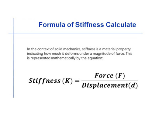
Imagine a precision machine tool doing a slow, steady cut. In this quasi-static state, the accuracy at the cutting tool is perfectly dictated by static stiffness: δ = F / κ.
But the real world is chaotic. The spindle revs up, the cutting tool violently slams into the workpiece, and the motors rapidly reverse direction. The load is no longer constant; it is varying over time. Your structure is no longer dealing with "static equilibrium"—it is now fighting forced vibration.
If the frequency of these operating forces gets anywhere near the structure's natural frequency, the amplitude of the vibration can be violently amplified by 10 to 50 times [1].
When engineers say a machine has "good static stiffness but poor dynamic stiffness," they don't mean the metal is suddenly turning soft. They mean the ratio between the machine's stiffness and its mass was poorly designed, causing its natural frequency to sit dangerously close to its everyday working speed.
II. Single Degree of Freedom (SDOF) Dynamics: The Essence in a Few Equations
2.1 The Classic Equation
To understand this, we use the simplest model in physics: the Single Degree of Freedom (SDOF) mass-spring-damper system. Its behavior is governed by:

It relies on three actors: Mass m (inertia), Damping c (energy absorption), and Stiffness k (elastic recovery).
2.2 Natural Frequency (ωn)
If we remove damping (c=0) and external forces (F=0), we get the formula for free vibration. The natural frequency is dictated purely by stiffness and mass:

This is the holy grail formula of dynamic design. Look at what it tells us:
(1)Double the stiffness (k) → Natural frequency increases by 41% (√2-1).
(2)Cut the mass in half (m) → Natural frequency also increases by 41%.
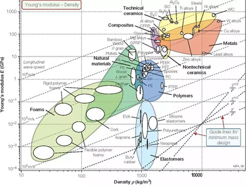
(3)The Catch: Making a structure stiffer usually means adding more metal (mass), which cancels out the gain. The true measure of dynamic quality is the ratio of k/m. For bending structures, this ultimately boils down to the material's E/ρ ratio (Elastic Modulus to Density). This "Specific Stiffness" is the secret weapon we will explore in Day 6.
2.3 The Damping Ratio (ζ)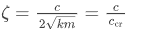
The damping ratio tells us how quickly vibrations die out.
(1)ζ<1 : Underdamped (it oscillates, slowly dying out).
(2)ζ=1: Critically damped (returns to zero as fast as possible without oscillating).
(3)ζ>1: Overdamped (sluggishly crawls back to zero).
Here is a harsh reality: Precision metal structures are almost permanently underdamped. Typical steel structures hover around ζ≈0.001-0.005. Solid metal lattices barely absorb any energy. In engineering, structural damping almost entirely comes from friction and micro-slipping at bolted joints. This tiny amount of damping isn't enough to stop a resonance disaster; it’s barely enough to let the vibrations eventually die out.
2.4 Dynamic Stiffness: The Slave to Frequency
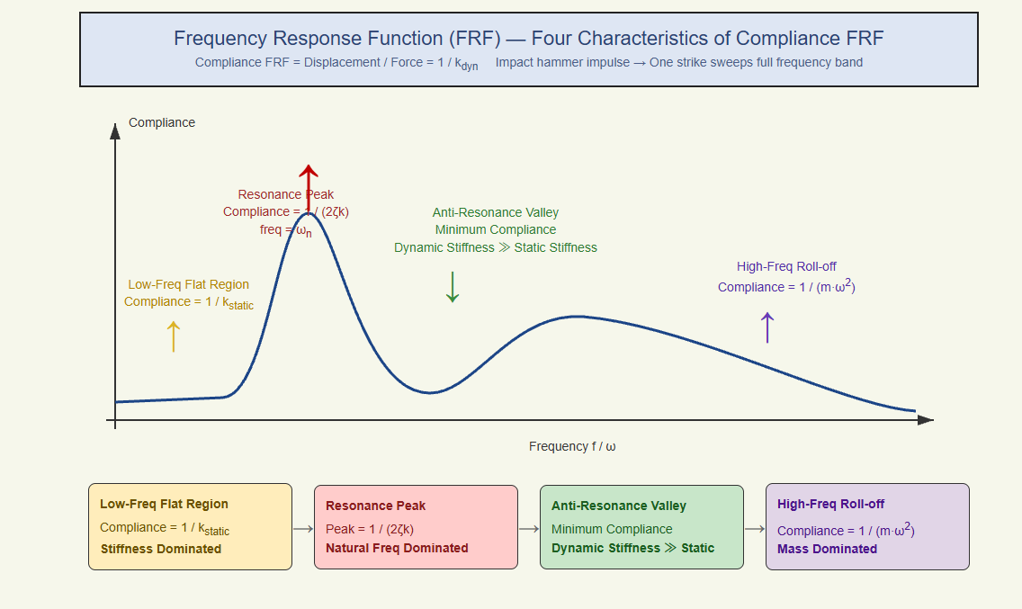
Under a vibrating load, the stiffness of your machine changes depending on how fast you shake it. This is Dynamic Stiffness (kdyn). We can break its behavior into three distinct zones [2]:
1.Low-Frequency Zone (ω≤ωn): kdyn≈k. The force is moving so slowly that inertia and damping don't really matter. The machine acts just like it does in a static test.
2.The Resonance Zone (ω≈ωn): Disaster strikes. Inertia and stiffness cancel each other out, and dynamic stiffness plummets to kdyn≈2ζk. If your damping ratio ζ is 0.01, your dynamic stiffness is suddenly only 2% of your static stiffness!
3.High-Frequency Zone (ω≥ωn): kdyn≈mω2. The shaking is so fast that the machine's mass (inertia) takes over. Every time you double the frequency, the dynamic stiffness quadruples.
The Engineering Takeaway: Your machine's working frequency (or interference frequency) can never be allowed to enter the resonance zone. Your only strategy is to design the machine's natural frequency to be vastly higher than its working frequency, keeping operations safely in the low-frequency, highly-stiff zone.
III. Multi-Degree of Freedom (MDOF): Finding the Real Shake
3.1 From One Spring to a Skyscraper
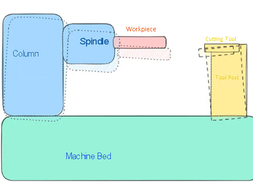
Real machines aren't a single spring and block; they are like multi-story buildings. Every floor has mass, every column has stiffness, and the whole building can twist and bend in multiple shapes at different frequencies.
By solving complex matrix equations (det ([K] - ω2[M]) = 0), software gives us multiple natural frequencies (ω1, ω2,..) and their corresponding "Mode Shapes."
3.2 Which Mode Shape is the Killer?
Not all resonances destroy precision. A mode is dangerous if:
1.Its frequency sits inside your operating bandwidth.
2.The vibration direction aligns with your sensitive measurement axis.
3.The physical cutting forces actually hit the machine in a way that triggers that specific shape.
The 1st mode (the fundamental frequency) is usually the deadliest because it has the lowest stiffness. In precision machinery, you'll often see:
1.A C-frame column nodding forward and backward (~50–200 Hz).
2.A spindle rocking inside its bearings.
3.The massive crossbeam of a gantry bending in the middle.
A raw frequency number (e.g., 120 Hz) just tells you a problem exists. An animated 3D mode shape tells you exactly where to weld on more steel to fix it.
IV. Reading the Frequency Response Function (FRF)
4.1 The Story an FRF Tells
The FRF is a graph that shows how the machine's displacement (output) reacts to a force (input) across a sweeping range of frequencies. To get this, engineers use an impact hammer. One tap of the hammer sends a pulse containing all frequencies into the machine, instantly generating the entire curve.
4.2 What to Look For:
1.The flat line on the left: Read this value to instantly know your static stiffness.
2.The giant peaks: These pinpoint your natural frequencies.
3.The sharpness of the peaks: This reveals your damping ratio ζ (calculated using the "half-power bandwidth" method).
4.Anti-resonance (The Valleys): Between two peaks, you'll find a deep valley. Here, dynamic stiffness is actually higher than static stiffness. High-level engineers will intentionally tune their servo motors to operate inside this valley to get "free" extra stiffness [3].
4.3 Experimental Modal Analysis (EMA) vs. FEA
Hammer + Accelerometer = EMA. You physically hit the machine and measure the shake. You must always compare this real-world data to your computer simulation (FEA):
1.If frequencies are off by >10%, your computer model assumed the bolted joints were too stiff.
2.If the shape is wrong, your assumption of where the mass is located is flawed.
3.Damping in FEA is always just an educated guess. EMA gives you the hard truth.
V. The War Between Servo Bandwidth and Resonance
Servo bandwidth is the speed limit of your machine's brain (the PID controller). A higher bandwidth means a faster, more accurate machine.
But if you push the servo bandwidth too close to the machine's mechanical natural frequency, the motor will begin to push and pull perfectly in time with the resonance, causing a violent self-excited vibration. Because of this, the physical frame dictates the absolute speed limit of the software [3]:
fservo< fn,1 / 3 to fn,1 / 5.
If your machine's fundamental frequency is 120 Hz, your servo can only safely run at 25–40 Hz. If you want a screaming-fast 100 Hz servo, you have to build a mechanical frame that resonates at 300–500 Hz.
How to raise the fundamental frequency (ranked by effectiveness):
1.Drop Weight (Lower m): Hollow out the structure. Maintain k while dropping m.
2.Add Stiffness (Raise k): Increase beam height or change how it is mounted (changing a cantilever beam to one supported on both ends can boost k by 64 times).
3.The Band-aid (Notch Filters): Use software to tell the motor to "ignore" the resonance frequency. This suppresses the shaking electronically, but it's a band-aid. It only fixes one frequency, and the moment the machine heats up and the metal expands, the physical frequency drifts, and the software filter becomes useless.
VI. Why Bring Up Damping Now?
Damping (c) does not change your natural frequency. However, it is the absolute dictator of how bad things get when you hit resonance.
Consider Cast Iron ( ζ ≈0.003-0.01) versus Welded Steel ( ζ ≈0.001-0.002).
Cast iron possesses 3 to 5 times more damping than steel. This means if both structures hit resonance, the cast iron machine will have 3 to 5 times more dynamic stiffness to fight off the violent shaking.
This is the exact reason why ultra-precision machine beds are poured from cast iron or polymer concrete instead of welded steel. It is not because cast iron is stiffer (its E value is actually lower)—it is because it absorbs vibrations, guaranteeing dynamic precision. We will dive deep into this magic in Day 6.
References
[1] Inman, D. J., Engineering Vibration, 4th ed., Pearson, 2014, Ch.2 "Response to Harmonic Excitation" (Contains the 3-zone FRF diagrams), Ch.3 "Vibration Isolation" (Contains force transmissibility curves).
(Note: This article is adapted from the WeChat public account "Mechanical Architect", edited for educational exchange. Copyright belongs to the original creator.)
[2] Schmidt, R. M., Schitter, G., & van Eijk, J., The Design of High Performance Mechatronics, IOS Press/Delft University Press, 4th ed., 2024, Ch.5 "Dynamics and Control" (Contains the analysis of the trade-off between servo bandwidth and structural resonance).
[3] Rivin, E. I., Stiffness and Damping in Mechanical Design, ASME Press, 2010, Ch.7 "Design Techniques for Reducing Structural Deformations".