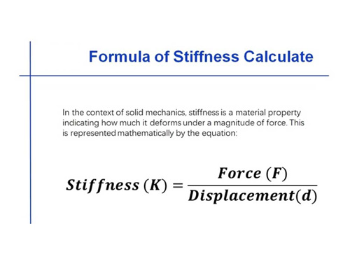
D02 Stiffness: The Skeleton Language of Precision Machinery
Day 3: Principles (Part 2)
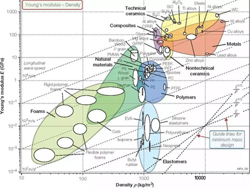
Yesterday, we talked about the ingredients of a machine—the Material (E) and the Cross-section (I). Today, we are diving into the third, and arguably the most overlooked, factor: Topology (Length L and the force flow path). Give two engineers the exact same pile of materials, and how they connect them can result in stiffness differences spanning several orders of magnitude.
I. The Structural Loop: Where Does the Force Come From, and Where Does It Go?
1.1 The Definition
The "Structural Loop" is a master concept systematically explained by Alexander Slocum in his seminal book Precision Machine Design [1]. Think of it as a journey:
It is the complete, closed-loop path that a force takes as it travels from a point of origin, passes through a series of structural components and mechanical interfaces, and finally arrives at another reference point (or returns to the start).
Every single segment along this path—be it a massive steel column, a tiny bolt, a linear guide, or a bearing—exists in a series circuit of force. The total stiffness of this entire loop is simply the inverse of the sum of all individual compliances (the opposite of stiffness) strung together:

1.2 Three Iron Rules of the Structural Loop
Looking straight at this series stiffness formula, we can deduce three unbreakable rules of design:
Iron Rule 1: The shorter the loop, the better. Every time you add a segment to the chain, you increase the total compliance (softness). A long force path means multiple segments in series, which guarantees lower total stiffness.
Iron Rule 2: The straighter the components, the better. Whenever the "flow" of force has to turn a corner, the loading mode switches from a simple, strong push-pull (tension/compression) into a complex bend or twist. In engineering, axial stiffness is inherently vastly superior to bending stiffness ( kaxial≥kbending, often by 2 to 3 orders of magnitude for slender parts).
Iron Rule 3: The fewer the joints, the better. Every bolted connection and every sliding rail interface acts as a squishy spring added to the series. As we will prove in Day 4, the contact stiffness of these joints is almost always the weakest link in the structural loop.
II. C-Frame vs. Gantry — How Topology Dictates Stiffness
Imagine you have the same material, the exact same cross-section, and the same machining precision. By simply changing the structural topology, your machine's stiffness can jump by a full order of magnitude. Let's look at the classic showdown.
2.1 The C-Frame
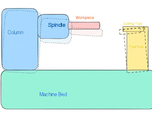
The primary charm of the C-Frame is its openness. It is accessible from three sides, making it incredibly easy to load and unload workpieces. But this convenience comes at a steep structural cost: the force flow is forced to take a massive "C-shaped" detour. The main column acts as a cantilever beam, bearing the full brunt of the bending moment.
If we look at the deflection (δ) at the tool tip under a cutting force (F), where H is the column height and L is the cantilever length from the column's centerline to the tool tip:

The first term is the column bending itself. The second term is trickier: the column bending causes an angular deflection at the top (θ=FH2/2EI), which is then heavily amplified by the cantilever arm L (becoming θ·L). Notice that both terms rely on high powers of H. In a C-Frame, column height is the ultimate enemy of stiffness.
2.2 The Gantry (Bridge) Frame
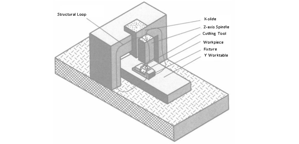
Now look at the Gantry Frame. Its force flow forms a closed rectangle. The crossbeam is supported at both ends, and dual columns share the vertical load in parallel. The deflection at the midpoint of the crossbeam looks like this [2]:
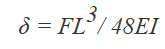
(if the ends are simply supported)
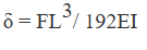
(if the ends are fixed)
Compare this to the C-Frame's . Just by changing the boundary conditions—going from a "cantilever" to "supported at both ends"—the deflection is slashed by 16 to 64 times (48/3 = 16; 192/3 = 64).
This is the sheer power of topology. We didn't use better steel; we didn't use better manufacturing. We simply changed the force path.
2.3 The Price of the Gantry
Of course, there is no free lunch in topology. The tremendous stiffness of the Gantry frame demands sacrifices:
Enclosed Space: The dual columns block the sides, severely restricting access to the workspace.
Synchronized Driving: The two columns must be driven simultaneously (or one must perfectly follow the other), heavily complicating the motion control system.
Thermal Asymmetry: If the two columns expand differently due to heat, they introduce entirely new dimensional errors.
In precision machine design, choosing between a C-Frame and a Gantry is a forever trade-off between accessibility and stiffness. Compact, ultra-precise machines dealing with light forces often use C-Frames. Massive machines dealing with heavy cutting forces? They have no choice but to go Gantry.
III. Visualizing Force Flow — Hunting Down Stiffness "Assassins"
3.1 How to Draw Force Flow Lines
Force Flow Lines are a brilliant semi-quantitative design tool [1]. You simply draw the path of force transmission on a cross-sectional diagram, treating the force exactly like a fluid rushing through pipes. The rules are beautifully intuitive:
Tension/Compression Zones: Lines run parallel to the load and are evenly spaced.
Bending Zones: Lines get densely packed on one side (compression) and sparsely separated on the other (tension).
Corners: To change direction, the flow requires transverse forces (bending), creating local stress concentrations.
Joints: As lines pass through contact surfaces, they are violently severed and must redistribute themselves.
3.2 The Fingerprints of Stiffness "Assassins"
When looking at a force flow diagram, watch out for these tell-tale signs that your stiffness is being quietly assassinated:
Sharp Turns: Force lines hitting a 90° corner generate bending moments. Usually, structures aren't ribbed in this specific direction (ribs are usually normal to the surface, but turning creates out-of-plane bending).
Sudden Section Changes: Forcing a wide river of force into a narrow bottleneck causes massive stress concentrations, making local compliance skyrocket.
Out-of-Plane Loads on Thin Walls: If force lines hit a thin plate perpendicularly, disaster strikes. A plate's out-of-plane bending stiffness is incredibly low (I ∝ t3), and compliance spirals out of control.
Bolt Crossings: Whenever force must cross a threaded joint, it falls victim to the series compliance of contact stiffness (the star of our upcoming Day 4).
IV. The Abbe Principle: A Stiffness Perspective
Traditionally, the Abbe Principle is taught as the golden rule of metrology: The measuring axis must be collinear with the axis of the dimension being measured; otherwise, any angular deflection will be amplified by the Abbe offset arm (L), resulting in first-order measurement errors [1].
The textbook example? A micrometer obeys the rule (δ = L·θ, the screw aligns with the measurement face), while a vernier caliper violates it (there is an offset between the scale and the jaws).
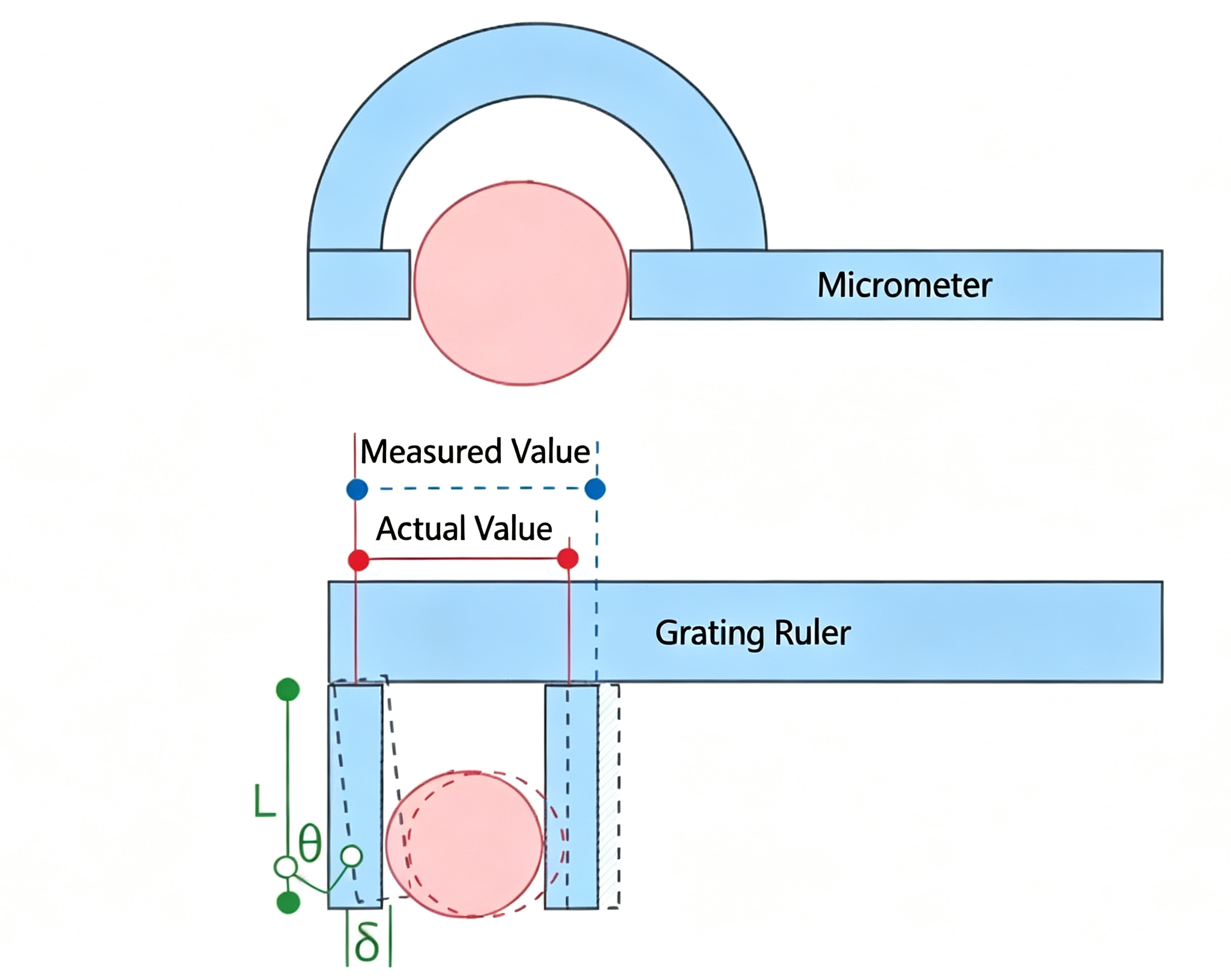
But dig deeper, and you'll find a profound structural logic hidden within. An Abbe offset doesn't just amplify measurement errors—it fundamentally changes how a structure handles loads.
When the measurement axis and the loaded axis are out of alignment, the offset introduces a bending moment. The structure is suddenly forced to fight the force by bending, and we already know kaxial≥kbending (often by 2–3 orders of magnitude) [1]. But when the axes are perfectly collinear, the force flows purely axially. The structure gets to fight the load using its absolute strongest mode.
Abbe Compliance = Transforming a bending stiffness problem into an axial stiffness problem.
This is arguably the most elegant "dimensionality reduction" strike in structural design. You don't need a higher I, and you don't need exotic high-E materials. You just topologically erase the bending moment from existence.
V. The 6-DOF Stiffness Matrix — Finding the Softest Link
5.1 Stiffness is Not a Scalar
In the real world, a structural node in 3D space has 6 degrees of freedom (DOF): 3 translations (x,y,z) and 3 rotations (θx, θy, θz). Therefore, its stiffness isn't a single number; it is a Matrix [1]:
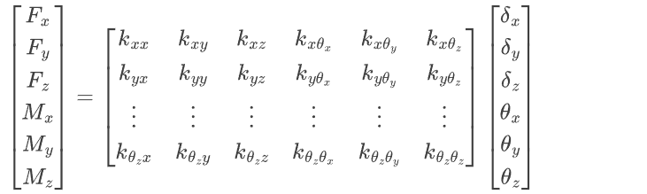
The diagonal elements (Kxx, Kyy, ……Kθzθz) represent the primary stiffness in each respective direction. The off-diagonal elements are coupling terms—meaning a force applied in one direction will actually cause deformation in another.
5.2 Hunting for the "Weakest Stiffness Mode"
One of the most critical analyses in precision machine design is performing an eigenvalue decomposition on this stiffness matrix. The eigenvector associated with the smallest eigenvalue reveals the structure's "Weakest Stiffness Mode." It loudly tells you:
In which direction the structure is most eager to deform.
Which specific loading pattern is the most dangerous.
Here is a classic trap: When analyzing a cantilever beam, everyone stares obsessively at the vertical bending stiffness (Kzz). But the torsional stiffness around the y-axis (Kθyθy) might be a full order of magnitude lower! Once that torsion causes an angular deflection, and that deflection is amplified by an Abbe offset at the far end, the resulting error can easily dwarf the simple vertical deflection. The most obvious direction is rarely the most dangerous one.
VI. Bridging D01 to D02: The Stiffness of Kinematic Interfaces
Last week in D01, we explored Exact Constraint (Kinematics)—how to use the absolute minimum number of contact points to constrain all degrees of freedom without creating redundant fighting forces. This week, we are talking about Stiffness (Dynamics)—the relationship between force and displacement. Where do these two worlds collide?
6.1 The Stiffness Matrix of a Maxwell Coupling
Take the legendary Maxwell Coupling: a bottom plate with three V-grooves and a top plate with three spheres, arranged symmetrically at 120°. Each V-groove provides 2 constraints, resulting in exactly 6 independent constraints—perfectly exact, completely non-redundant [3].
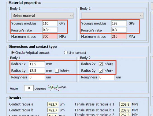
Each ball-to-groove interface is a Hertzian point contact, and its normal stiffness is dictated by:
kn = (6E2RF)1/3
The structural synthesis of these three contact points dictates the complete 6-DOF stiffness matrix of the coupling. The translational stiffness is a combination of the three kn values, while the angular stiffness heavily depends on kn · r2 (where r is the distance from the spheres to the coupling's center).
For context, a typical ∅25mm steel ball under 1000 N of preload offers a normal contact stiffness of about 2*108N/m, which translates to a system translational stiffness of roughly 107 to 108N/m.
6.2 The Master Design Parameters
The stiffness of a Maxwell Coupling is ultimately controlled by just three levers:
Sphere Radius R: kn ∝ R1/3(Bigger balls are stiffer, though with diminishing returns).
Preload F: kn ∝ F1/3(Higher preload means higher stiffness, limited only by the material's yield strength under Hertzian stress).
Sphere Spacing r: Angular Stiffness ∝ r2 (The further apart the balls, the drastically higher the angular stiffness—the maximum moment arm principle holds true in both D01 and D02).
This is the beautiful unification of Kinematic and Structural design: D01 tells you exactly where to put the contact points (managing degrees of freedom), while D02 tells you how big those points must be and how hard to press them together (managing stiffness).
References
[1] Slocum, A. H., Precision Machine Design, SME, 1992. §7.4 (Structural loop concepts and stiffness comparison between C-Frame and Gantry structures), §2.2–2.3 (Abbe error principles and diagrams). Note: This article is adapted from the WeChat public account "Mechanical Architect" with minor modifications for educational exchange. Copyright belongs to the original creator.
[2] Rivin, E. I., Stiffness and Damping in Mechanical Design, ASME Press, 2010. Ch.2 "Stiffness of Structural Components", Ch.6 "Design for Stiffness".
[3] Hale, L. C., Principles and Techniques for Designing Precision Machines, PhD Thesis, MIT, 1999. Ch.3 "Structural Design" (Design principles for independent stiffness structures), Ch.7 "Design Methodology" (Complete workflow for precision machine design).