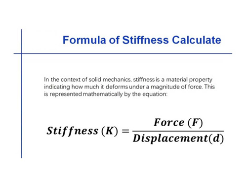
Welcome to Day 4: The Critical Nodes.
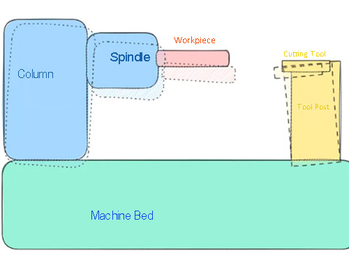
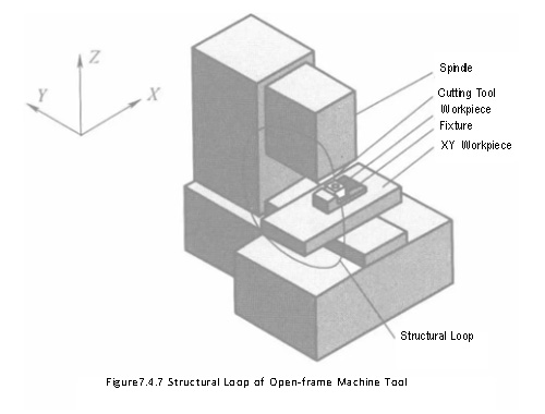
When you calculate the structural stiffness of a machine on a computer, you are usually assuming that the whole system is carved from a single, solid block of material. The reality? Machines are bolted together. Every single joint and connection acts as a flexible spring sneaking into your system in series. Today, we are going to hunt down these "invisible flexibilities" one by one and quantify the exact damage they do to your machine's precision.
I. The Meeting of Two Surfaces: The Microscopic Reality
1.1 Flat is Never Truly Flat
To the naked eye, a freshly machined metal surface looks perfectly smooth. Under a microscope, however, it resembles a rugged landscape of mountains and valleys. Even with precision grinding achieving a roughness of Ra≈0.4-0.8μm, the heights and spacing of these microscopic peaks (known as asperities) are entirely random.
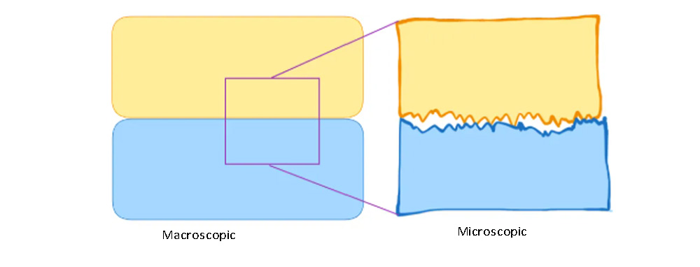
When you press two of these surfaces together, they don't actually touch across the entire nominal area. Only the highest mountain peaks crash into each other. The actual contact area is typically only 0.1% to 1% of the nominal area [1].
What does this mean for precision?
That tiny 0.1% area bears 100% of the load. The local pressure easily approaches or exceeds the material's yield strength.
The elastic (and localized plastic) crushing of these peaks creates "extra displacement" at the joint.
This extra displacement means the effective stiffness is drastically lower than what you calculated for a solid piece of metal.
This physical phenomenon is the root cause of Contact Stiffness.
1.2 The Greenwood-Williamson Model
In 1966, Greenwood and Williamson created a classic model for rough surface contact that yielded three crucial engineering takeaways [2]:
Pressure dictates real area: The actual contact area is almost perfectly proportional to the applied normal force (Ar ∝ Fn). As pressure increases, shorter peaks are forced into contact.
Stiffness grows non-linearly: Contact stiffness increases with load, but not linearly (kn ∝ Fnm , where m ≈ 0.5-0.7, depending on the surface topography).
Smoothness pays off: Under the exact same pressure, a smoother surface yields higher contact stiffness because the microscopic peaks are wider and flatter (larger radius of curvature).
II. Hertzian Contact: The Math of Spheres and Cylinders
2.1 Point Contact (Sphere on a Plane)
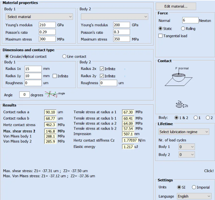
When a perfect sphere (radius R) presses into a flat plane, we use Hertz's classic equations to map the elastic deformation [1].
The contact zone becomes a tiny circle with radius α,
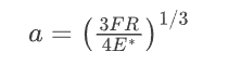
where:E* is the Equivalent Elastic Modulus (accounting for the materials of both parts):
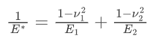
The normal approach (δ, how far they squish together) and the resulting normal contact stiffness (kn) are defined by these formulas.
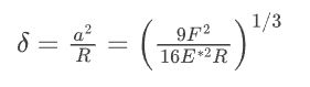

The Key Takeaway: kn ∝ F1/3 andkn ∝ R1/3 .
This represents brutal diminishing returns. If you increase the clamping force from 100 N to 800 N (an 8x increase), the stiffness only doubles (81/3=2). If you swap a 5 mm steel ball for a massive 40 mm ball, your stiffness still only doubles. Bigger balls and higher forces make things stiffer, but the leverage is a weak 1/3 power.
2.2 Line Contact (Cylinder on a Plane)
When a cylinder (radius R, length L) presses against a flat plane, the math shifts favorably.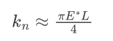
Unlike the sphere, stiffness here scales directly with the length of the cylinder (L is to the first power). Increasing the contact length is the absolute most effective way to boost line contact stiffness. This is the fundamental mechanical reason why cylindrical roller bearings are inherently stiffer than ball bearings.
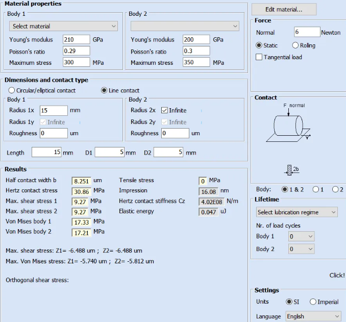
2.3 A Quick Engineering Calculation
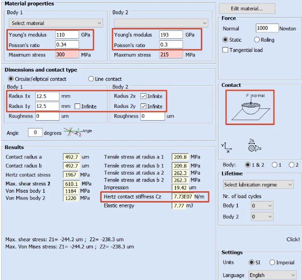
Imagine pressing a TC4 Titanium sphere (R=12.5 mm,E=100 GPa,v=0.34) against a flat SUS304 Stainless Steel plate (e=193 GPa, v=0.30).

If you apply a preload of F=1000 N, using Hertzian formulas, the normal stiffness kn calculates out to roughly 7.7x10⁷ N/m.
Kn = (6·(78x109)2 · 0.0125 · 1000)1/3 ≈ 7.7 x 10⁷ M/m
III. Bolted Joints: The VDI 2230 Compression Cone
3.1 A Bolt is Just a Chain of Springs
When you bolt two parts together, you are actually stringing several flexible springs together in series [3]:
The stretching of the bolt shank itself (kb = EbAb / Lb).
The thread engagement zone (Hertzian contact + bending of the threads).
The contact under the bolt head/nut.
The contact between the clamped parts (This is the most critical and hardest to calculate).
3.2 The Compression Cone Model
The industrial standard VDI 2230 solves this by assuming the clamping force spreads out through the metal in the shape of a cone (the Compression Cone). The angle of this cone depends on the material: roughly 26°–33° for steel, 22°–30° for cast iron, and 17°–25° for aluminum.
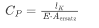
The formula relies heavily on the Clamping Length (lK).
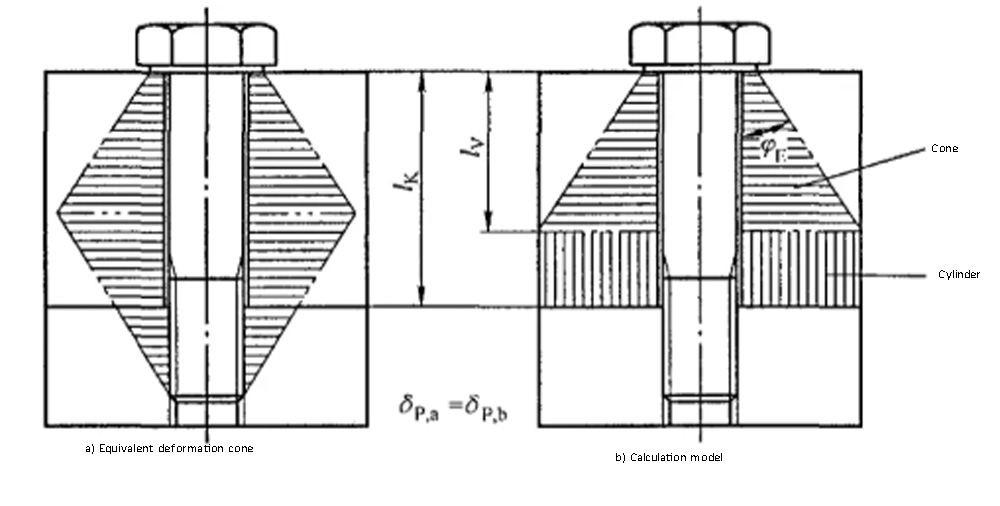
Here is a counterintuitive secret: the longer the bolt, the stiffer the joint. A longer clamping length allows the compression cone to spread out wider. A wider cone means a larger equivalent cross-sectional area, which translates to a stiffer connection. Short, stubby bolts actually struggle to provide good contact stiffness because the cone gets cut off before it can fully expand.
3.3 Preload: The First Line of Defense
Contact stiffness lives and dies by contact pressure. The preload force (FM) directly dictates this pressure. Rivin's experimental data paints a stark picture [3]:
If preload drops by 30%, contact stiffness can plummet by more than 50%.
Improving surface roughness from Ra=3.2μm to0.8μm boosts stiffness by 30%–50% under the same preload.
The Rule: Slightly over-tightening a bolt (safely below yield strength) is always better than under-tightening. Under-tightening doesn't just risk the bolt rattling loose; it causes an immediate collapse in structural stiffness, destroying your machine's precision long before the bolt actually fails.
IV. Pushing vs. Sliding: The Anisotropy of Joints
4.1 The Mechanics of Tangential Stiffness
When two rough surfaces are compressed, the microscopic peaks interlock. But if you push them sideways (tangential force), they want to slide. This involves elastic bending of the peaks plus microscopic sliding (microslip) [1].
In engineering, tangential stiffness (kt) is inherently crippled compared to normal stiffness (kn).For dry, unlubricated metals:
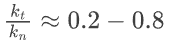
Joints are naturally weak against sideways sheer.
4.2 Why This Destroys Precision Positioning
You might think a high-res linear encoder (sensor) can just compensate for this sloppy tangential stiffness. It can correct the final static position, but tangential flexibility ruins your machine in three dynamic ways:
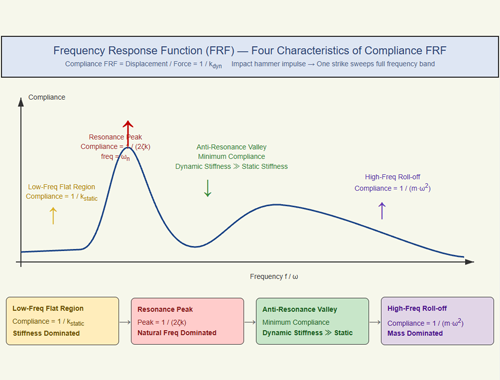
It kills Servo Bandwidth: Tangential flexibility acts like a squishy spring between your motor and the load, creating a low-frequency mechanical resonance (ωr = √ (kt / m)). To prevent violent vibrations, you have to tune your servo bandwidth down to ωr / 3. A lower kt means a slower, sloppier motor response.
It ruins Disturbance Rejection: When the machine suddenly hits a hard piece of metal (cutting force jump), there is a millisecond delay before the sensor tells the motor to fight back. A low kt means the machine physically deflects much further during that tiny window of time.
Non-Servo Blind Spots: Joints like the spindle-to-tool-holder or workpiece-to-fixture aren't monitored by sensors. Any tangential flexing here directly permanently ruins the workpiece.
V. Hysteresis: The Crooked Line of Stiffness
5.1 Force and Displacement Don't Match
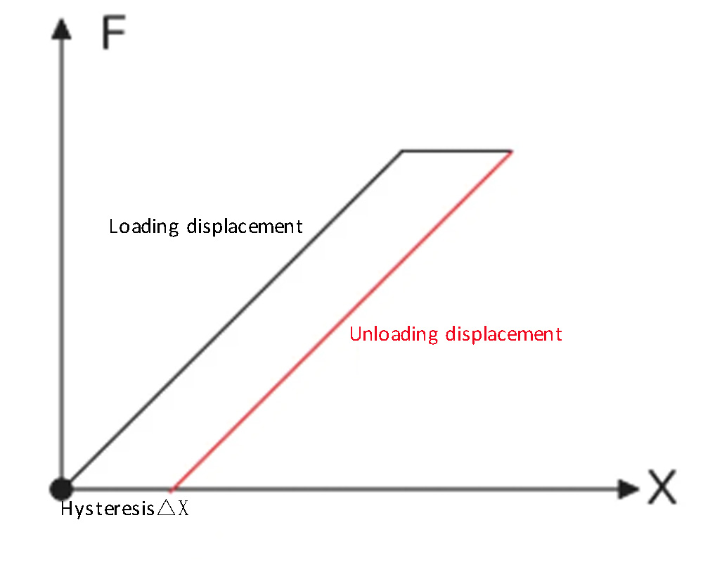
One of the biggest headaches in contact mechanics is that the loading path and the unloading path are never the same. When you map force against displacement, they form a loop—a Hysteresis Loop [3].
5.2 Where Does Hysteresis Come From?
Microslip: Before the whole joint slides, the outer edges of the contact zone begin to slip microscopically, burning off energy.
Plastic Deformation: The tallest microscopic peaks get permanently crushed on the first load and don't bounce back.
Internal Friction: Atomic dislocations and thermoelastic effects inside the metal lattice.
5.3 The Absolute Limit of Precision
The width of this hysteresis loop (δhyst) dictates the absolute rock-bottom limit of your machine's repeatability. For precision-ground steel-on-steel joints, this loop is usually 0.1 to 1 μm wide.
This means your mechanical uncertainty is permanently stuck at 0.1–1μm. You cannot "manufacture" your way out of this with better CNC machines—it is dictated by the intrinsic laws of physics. (Pro-tip: Adding lubricating oil fills the microscopic gaps and can cut this hysteresis width in half).
VI. The FEA Trap and How to Actually Fix It
6.1 The FEA "Black Box"
Simulating solid metal stiffness in Finite Element Analysis (FEA) is highly accurate. Simulating contact stiffness is a guessing game [3].
Switching between contact algorithms (Penalty Method vs. Lagrange) can change your results by 300%. A slight tweak in the friction coefficient (from 0.1 to 0.3) shifts tangential stiffness by 50%. Since engineers rarely input exact microscopic topography data into software, FEA contact results must be calibrated with real-world physical testing.
6.2 The Ultimate Fixes (Ranked by Priority)
Kill the Joints: If you can weld it, weld it. If you can machine it from one block, do it. Modern 3D printing and topology optimization allow for massive, monolithic frames with zero bolts.
Use Discrete Contacts: Massive flat flanges often create"over-constraint" (battling forces). Instead, use 2 or 3 distinct, separated contact points (like kinematic Sphere-V-groove couplings).
Max Out the Preload: Take bolts right up to their safe yield limit using precise torque-angle methods or hydraulic tensioners.
Grind it Smooth: Precision grind mating surfaces down to Ra<0.8μm.
Use Epoxy Grouting: Pouring structural epoxy into the gaps between cast iron beds and columns permanently locks the joint.
Re-route the Force: A flexible joint is only a disaster if it sits right in the main path of the physical load. Design your structure so the heavy forces flow around the bolted connections, not through them.
The Golden Rule: If you realize in the design phase that a bolted joint is going to act as a weak, series spring, don't try to bandage it later. Redesign the topology. Make the physical force bypass the joint entirely.
References
[1] Johnson, K. L., Contact Mechanics, Cambridge University Press, 1985, Ch.4–5. (The complete analytical solutions for Hertz point and line contacts; the original source for the sphere-plane stiffness formula in this text.)
[2] Greenwood, J. A. & Williamson, J. B. P., "Contact of Nominally Flat Surfaces," Proc. Royal Society A, Vol. 295, 1966, pp. 300–319. (The original paper on the GW model for rough surface contact, containing comparison charts of actual vs. nominal contact area.)
[3] Rivin, E. I., Stiffness and Damping in Mechanical Design, ASME Press, 2010, Ch.4 "Contact (Joint) Stiffness and Damping". (Contains experimental data charts for bolted joint contact stiffness, serving as the quantitative basis for the preload-stiffness relationship discussed here.)
[4] VDI 2230 Part 1, Systematic Calculation of Highly Stressed Bolted Joints, 2015. (Contains the compression cone model diagram and serves as the industrial standard for calculating bolted joint flexibility.)