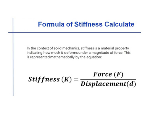
Day 1 Prologue: From Strength-Thinking to Stiffness-Thinking—Why a precision engineer's biggest nightmare isn't a broken machine, but a slightly bent one.
I. Opening: Two Designers, Two Kinds of Anxiety
Let’s imagine two mechanical designers, both facing the challenge of designing a cantilever load-bearing structure.
The first designer is working on a temporary support bracket for a construction site. His calculation process is straightforward: calculate the maximum bending moment → check the material's yield strength → apply a safety factor of 2.5 → select the cross-section → done. He only cares about one question: Will this structure break? Whether it deflects by 5 mm or 10 mm doesn't matter; it will be torn down once the concrete is poured anyway.
The second designer is engineering the bridge (crossbeam) of a Coordinate Measuring Machine (CMM). He also calculates the maximum bending moment, checks the yield strength, and applies a safety factor—but this is not his primary calculation. His very first question is: When the probe moves to the furthest end of the bridge, how much deflection is caused by gravity? If the answer is 5 μm, this CMM is already a failure. Why? Because the measurement accuracy requirement is ±2 μm. The structural deformation caused merely by the bridge's own weight has already eaten up the entire Error Budget.
The difference between these two designers perfectly illustrates the divide between "strength-thinking" and "stiffness-thinking."
In general mechanical design, stiffness is an afterthought—once the strength is verified, stiffness is just a quick double-check. In precision engineering, this order is entirely flipped: stiffness is the ultimate metric, and strength is merely the baseline for survival. The column of a precision machine tool might boast a massive safety factor of 8 for strength, but if the cutting force causes the tool tip to shift by more than 10 μm, the machine is completely worthless to the customer. It is "incredibly safe" in terms of strength, but "an absolute failure" in terms of precision.
Eugene I. Rivin put it bluntly in the opening of his book Stiffness and Damping in Mechanical Design [1]:
"In many engineering applications, especially in precision machinery, stiffness is the most important design parameter, often far more critical than strength."
II. Stiffness: The Underlying Physics of Precision
What is the ultimate pursuit of precision machinery? Geometric certainty. You want the functional tip—whether it’s a cutting tool, a measurement probe, an objective lens focus, or a laser spot—to be exactly where you command it to be, keeping any errors strictly within an allowable range.
So, what destroys this geometric certainty? Force. Cutting forces, inertial forces, gravity, thermal stress, and assembly stress—all these forces act upon the structure and cause displacement:
δ =F / κ
This simple equation is the foundational physics of precision. The force (F) might come from the outside (machining forces, acceleration) or from within (gravity, constrained thermal expansion, the release of bolt preload). Stiffness (k) is the only "denominator" you can actually control. You cannot eliminate all forces (gravity and cutting forces will always exist); all you can do is ensure that the same amount of force results in a much smaller displacement.
The formula above is a simplified 1D scenario. In real-world structures, every single node possesses six degrees of freedom (three translations: x, y, z + three rotations: θx, θy, θz). Therefore, stiffness is not a mere scalar number; it is a 6x6 matrix [2]:
F= K·δ
Here, both {F} and {δ} are six-dimensional vectors (translations + rotations), and [K] encompasses the stiffness in all directions, as well as the coupling terms between them. The "weakest direction" of a precision structure is rarely what your intuition suggests. The most fatal deformation mode of a cantilever beam might not be vertical deflection, but rather the angular deflection at the end caused by torsion. (This tiny angle is then magnified by the Abbe offset into a massive linear error).
III. Two Scenarios, One Root Cause
Let’s look at two classic scenarios in precision machinery. They look completely different, yet their failure mechanisms are identical.
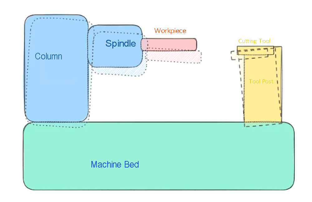
Scenario 1: The Tool Tip of a CNC Machine
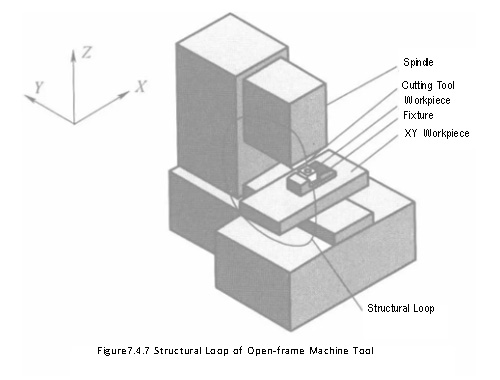
The spindle transmits the cutting force, the column withstands the bending moment, and the machine bed bears the gravity.
The displacement error of the tool tip relative to the workpiece = the sum of the deformations from every segment along the path of the force flow.
Typically, the bending deformation of the column is the biggest culprit. If the cross-sectional area moment of inertia (I) of your column isn't large enough, the entire structural loop will deform under the cutting force. This causes relative displacement between the tool tip and the workpiece, resulting in a machined outer diameter that is larger than intended. (Refer to Slocum §7.4 for structural loop analysis [2]).
Scenario 2: Gravity Deflection of a CMM Bridge
In §1.6 of his book, Slocum uses the CMM as a prime design case study, providing structural diagrams of a moving-bridge CMM [2]. When the probe travels to the far end of the bridge, the deflection caused by gravity is the absolute primary design constraint. The force flows from the probe → saddle → bridge → column → bed → workpiece. The bending deformation of the bridge translates directly into measurement error. This is not a manufacturing accuracy issue—you can machine the bridge to a geometric precision of 10 μm—this is purely a stiffness issue.
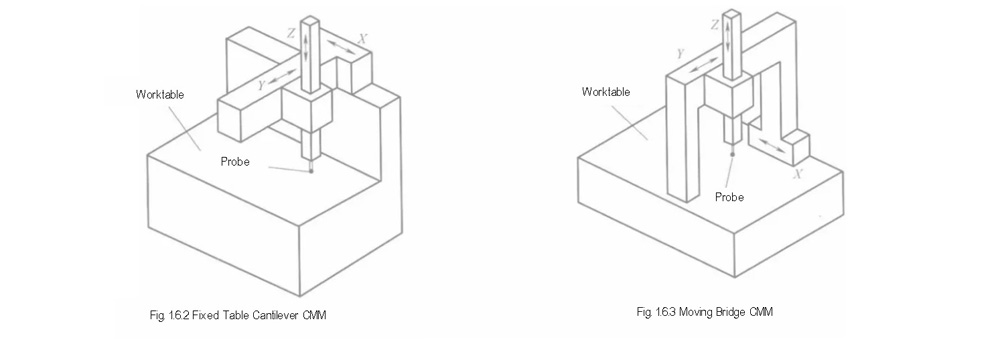
Slocum goes further in §2.2–2.3, providing a quantitative analysis and diagrams of the Abbe error [2]. When there is an Abbe offset between the axis of measurement and the axis of the encoder scale, the angular deflection (θ) caused by the bending bridge is amplified by the Abbe arm length (L) into a first-order measurement error: δ = L • θ.A 1 μrad angular deflection × a 100 mm Abbe arm = 100 nm of error. For a sub-micron CMM, this is completely unacceptable. The solution? Make the measurement axis collinear with the measured axis—achieving Abbe compliance.

The shared root cause in both scenarios: As force flows through a structure, displacement errors accumulate every time it passes through a flexible component. This is why stiffness is never just the property of a single part; it is the property of the entire force flow path. It is a "system-level physical quantity."
IV. Stiffness is Not a Material Property, It's a System Property
If you remember only one thing this week, make it this cognitive anchor.
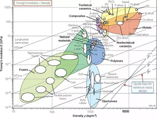
When selecting materials, many engineers will say: "Steel has higher stiffness than aluminum, so precision structures must use steel." This intuition is only half-right. The Elastic Modulus (E) of steel (E ≈ 200 GPa) is indeed nearly three times higher than that of aluminum alloy (E ≈ 70 GPa). But stiffness is about much more than just E.
Look at the deflection equation for a cantilever beam under a concentrated point load at its end: δ =FL3/3EI
(1)E is the material factor.
(2)I is the geometric factor (Area Moment of Inertia).
(3)L is the topological factor, representing the length of the force flow path.
These three factors contribute equally to stiffness and are interchangeable. Let's see what happens if we want to reduce deflection:
(1)Replace aluminum with steel: E increases by 3x → Deflection drops to 1/3.
(2)Change a solid round bar to an equal-weight hollow tube (Wall thickness/Outer diameter = 0.15): I increases by ~2.9x → Deflection drops to ~1/3.
(3)Change the cantilever support to a simply supported beam (supported at both ends): The effective L is halved, and the boundary condition changes the denominator from L3/3 to L3/192 → Deflection drops to 1/64!
The payoff from the third option far exceeds the first. The leverage that geometry and topology have on stiffness vastly outweighs mere material substitution. This is the ultimate secret of stiffness design.
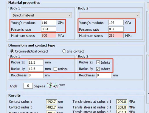
There is also a hidden factor: Contact Stiffness. The structural stiffness you calculated assumes all parts are magically welded together into one continuous block. In reality, your machine is bolted together. Every bolted joint introduces a flexible spring into the series. Structural stiffness + contact stiffness + bearing stiffness + guide rail stiffness... once chained together in series, the total stiffness is entirely dictated by the weakest link (1/ ktotal = ∑ 1/ ki). We will dedicate Day 4 entirely to this topic, as the weakest stiffness link in precision machinery is rarely the structural components, but the joints.
V. Four Questions for the Week Ahead
As we wrap up today's prologue, please keep these four questions in mind as we dive into the next six days:
(1)Where does your machine's stiffness come from? Is it E, I, L,or the joints? Which one is the true bottleneck in your current design?
(2)Where is the weakest link? In a series system, the softest spring dominates the total stiffness. Find it, and reinforce it.
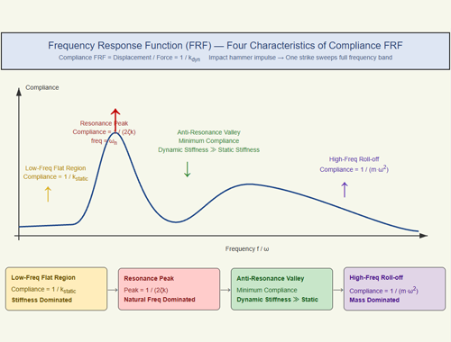
(3)Which governs your precision: Static or Dynamic stiffness? For slow movements, look at static stiffness; for high-speed operations, look at natural frequencies and damping.
Are your material and geometry choices correct? Under your given constraints, have you made the optimal structural topology choices?
This week, we will journey from Material → Geometry → Topology → Contact → Dynamics → Material Selection → Conclusion. By Day 7, you will possess a complete diagnostic toolkit for stiffness design.
References
[1] Rivin, E. I., Stiffness and Damping in Mechanical Design, Marcel Dekker, 1999, Ch.1 "Introduction". (The core monograph on stiffness design in precision machinery. ASME Press published an updated edition in 2010.)
[2] Slocum, A. H., Precision Machine Design, Society of Manufacturing Engineers, 1992. §1.6 (CMM design case and structural diagrams), §2.2–2.3 (Abbe error principles and diagrams), §7.4 (Structural loop concepts). (The classic textbook on precision machine design, and the original source for the two scenarios in this article.)