Welcome to Day 2 of our deep dive into stiffness—the fundamental language of precision machinery.
When you look at any structural beam, its stiffness is born from a simple marriage: the material it's made of, and the shape you design for it. Today, we're going to tear these two multiplication factors apart. In doing so, we'll uncover a truth that often goes under the radar: when it comes to making things stiff, the leverage of clever geometry completely overpowers your choice of material.
I. The Four Faces of Stiffness
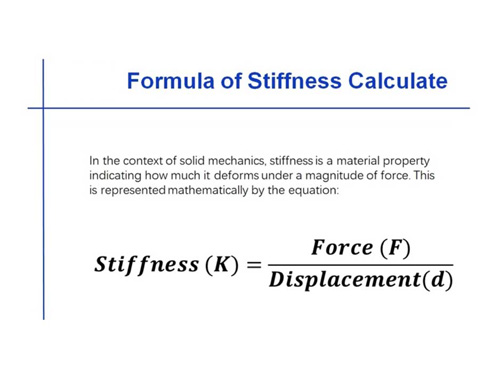
At its core, stiffness is just the ratio of force to displacement: κ = F / δ. But depending on how you apply that load, the engineering story changes drastically.
| Type | Formula | Controlling Factor | Typical Scenarios |
| Axial Stiffniss | ka=EA/L | Cross-sectiongal Area A | Tie rods,columns under compression |
| Bending Stiffness | kb=EA/L3 | Moment off Inertia I | Beams,cantilevers,frames |
| Torsional Stiffniss | kt=GJ/L | Polar Moment of Inertia J | Drive shafts,eccentrically loaded frames |
| Shear Stiffniss | ks=GA/α | CRoss-sectiongal Area A,Shape Factor α | Short stubby beams,honeycomb cores |
In the world of precision machinery, bending stiffness is the ultimate battleground. Almost every deformation that ruins a machine's precision happens when things bend.
Here is a crucial design secret: a component's axial stiffness (its resistance to being stretched or compressed) is usually hundreds of times greater than its bending stiffness (EA / L ≥ EI/L3 for slender members). Therefore, a master designer’s first instinct is always to try and convert bending forces into axial forces. Unfortunately, as we'll see in Day 3 (Structural Loops), the physical layout of machines often makes this a frustratingly impossible task.
II. Material Stiffness: The Physical Reality of E
Let's talk about Young’s Modulus, or E. This number tells you how well a material resists elastic deformation. Physically speaking, it represents the stiffness of the invisible bonds connecting atoms. In the elastic region of a stress-strain curve (E = δ / ℇ), it is the amount of stress required to "pull atoms apart" per unit of strain.
2.1 The E Ranking of Common Materials
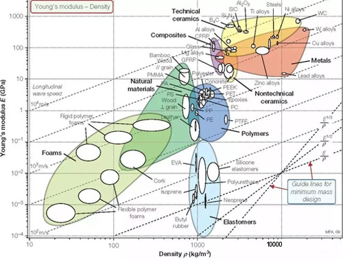
Let's see how different materials stack up. Here they are, ranked by their elastic modulus from highest to lowest [3]:
| Material | E (GPa) | G (GPa) | ν | Density (kg/m3) |
| Silicon Carbide (SiC) | ~450 | ~190 | 0.17 | 3200 |
| Aluminum Oxide (Al2O3) | ~380 | ~160 | 0.22 | 3900 |
| Beryllium (Be) | ~300 | ~135 | 0.1 | 1850 |
| Structural Steel | ~200 | ~79 | 0.3 | 7800 |
| Gray Cast Iron | 110-140 | 45-55 | 0.26 | 7200 |
| Invar Alloy | ~140 | ~54 | 0.29 | 8100 |
| Titanium Alloy (Ti–6Al–4V) | ~110 | ~42 | 0.34 | 4400 |
| Zerodur Glass-Ceramic | ~90 | ~37 | 0.24 | 2500 |
| Aluminum Alloy | ~70 | ~27 | 0.33 | 2700 |
| Granite | 40-80 | 15-30 | 0.20-0.30 | 2800-3000 |
| Magnesium Alloy | ~45 | ~17 | 0.35 | 1800 |
| Polymer Concrete | ~30-50 | 12-20 | 0.25-0.30 | 2200-2500 |
2.2 A Counterintuitive Truth
Here is a fact that often shocks beginners: within the same family of alloys, E is practically constant. You can tweak the chemical composition or heat-treat a piece of steel until it’s incredibly strong and hard, but its elastic modulus won't budge [1].
Low-carbon steel (Q235): E≈210 GPa
Alloy steel (42CrMo): E≈210 GPa
Stainless steel (SUS304): E≈193GPa
Tool steel (T10): E≈205 GPa
Imagine spending a fortune selecting high-strength steel and applying complex quenching treatments, hoping to make your machine frame "stiffer." The harsh reality? The E value doesn't move an inch. The material multiplier for stiffness is permanently locked the moment you choose steel. If you want a stiffer machine, your only way out is geometry.
2.3 The Relationship Between E , G, and ν
For isotropic materials (materials that behave the same in all directions):
G = E / 2(1+ν)
The Shear Modulus (G) is always smaller than E. For most metals, Poisson's ratio (ν) is around 0.3, meaning G ≈ 0.38E. This reveals that a material is naturally weaker against shearing than it is against pulling or pushing. This is the physical root cause of why torsional (twisting) and shear forces so easily compromise structural designs.
III. Geometric Stiffness: The "Fourth-Power Leverage" of Shape
If the material (E) is the hand you are dealt in a game of poker—unchangeable once the game starts—then the cross-sectional shape (I) is how you play the game. It is your ultimate design weapon.
3.1 The Physics of the Moment of Inertia
I = ∫Ay2dA
Here is the intuitive breakdown: for any given piece of material, the further away it is placed from the center (the neutral axis), the harder it fights bending. Because the distance (y) is squared in the formula, moving material to the outer edges yields exponential, squared gains in stiffness.
3.2 Quick Rules of Thumb for Design
(1)Solid Rectangles (height h, width b):
Ix = bh3 / 12
The height h is cubed. This leads to the golden rule of beam design: make it tall, not wide. If you simply double the height of a beam, it becomes 8 times stiffer.
(2)Solid Cylinders (diameter D):
I = πD4 / 64
The diameter is raised to the fourth power. Just a 26% increase in a rod's thickness will double its stiffness. This is why a slightly "thicker rod" might look similar to the naked eye but performs drastically better.
(3)The Magic of Hollow Tubes (outer D, inner d):
I = π(D4 - d4) / 64 = πD4 / 64 [ 1 - (d / D)4]
Imagine a tube where the wall thickness is only 10% of its total diameter (meaning d / D = 0.8).
1 - (0.8)4 = 1 - 0.41 = 0.59
This thin-walled tube keeps 59% of the stiffness of a solid rod of the exact same size. But look at what happens to the weight:
mtube / msolid = 1 - (d/D)2 = 1- 0.64 = 0.36
It only weighs 36% as much as the solid rod! The specific stiffness (stiffness-to-weight ratio) jumps to
0.59/0.36=1.64—a massive 64% improvement over a solid chunk of metal.
This is the absolute magic of hollow structures: they retain the vast majority of their rigidity while shedding most of their mass. In extreme cases (infinitely thin walls), a tube's specific stiffness is double that of a solid rod [1].
3.3 The Bending Efficiency Leaderboard for Common Shapes
If we keep the cross-sectional area exactly the same (which means the total weight remains identical), here is how the relative bending strength of various shapes stacks up [2]:

Designers must engrave this into their intuition: the hollow circular tube is the golden geometry for bending stiffness. It puts every ounce of material exactly where it works hardest on the outside, leaving no "freeloading" material in the center.
IV.The Dual-Core Engine of Precision Design
While I handles bending, J (Polar Moment of Inertia) handles twisting. If clever geometry can boost bending stiffness by tens of times, it can boost torsional stiffness by hundreds or thousands of times.
4.1 Torsion of Closed Thin-Walled Sections (Bredt's Formula)
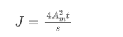
When engineers need to calculate how well a closed, hollow shape resists twisting, they rely on a beautiful piece of math known as Bredt's Formula [2]:

In these equations, Am represents the area trapped inside the centerline of the tube's walls, and t is the wall thickness itself.
If you are designing a shape where the wall thickness (t) is uniform all the way around, the math for the torsional constant (J) simplifies elegantly:
4.2 Torsion of Open Thin-Walled Sections
But what happens if the shape is "open"—like a standard I-beam or a C-channel built from narrow, flat steel plates? The physical rules change drastically:
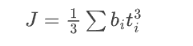
Pay close attention to the thickness t in that equation. For open sections, it is cubed. In structural physics, this tells us a harsh truth: thin means extremely flexible.
4.3 The Hundredfold Chasm
Let’s look at a jaw-dropping real-world calculation to see how this plays out.
Imagine a standard, closed circular steel tube with an outer diameter of 50 mm and a 2 mm wall thickness. Its torsional stiffness is massive:

Now, imagine taking a saw and cutting a single, hair-thin slit straight down the length of that tube. It's no longer a continuous loop; it's now an open shape. Let's run the numbers again:

The gap: 260 times. A single open slit instantly annihilates every single torsional advantage that the closed tube originally possessed [1].
This brutal mathematical reality perfectly explains why the structural frames of high-precision machines are almost universally built from completely closed, box-like beams. It’s not a matter of lacking better design options; it's simply because the moment an open structural section is subjected to an off-center, twisting load, it deforms as easily as Play-Doh.
V. The Iron Laws of Assembly: Series vs. Parallel
5.1 The Weakest Link (Series Springs)
When forces pass through components sequentially—with only one single path to follow—they are in series:
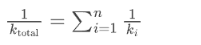
This is the most brutal mathematical reality in precision machinery. Imagine a machine with 10 sequential links. Nine of them are incredibly stiff (109 N/m), but one is flexible (106 N/m).
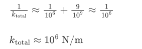
That single weak link dominates the equation, dragging the stiffness of the entire multi-million-dollar system down to its level. In precision engineering, bolted joints are the ultimate "stiffness assassins." A joint's contact stiffness is often 1 to 2 orders of magnitude lower than the solid metal structure. The moment that joint is added in series, it ruins everything.
5.2 Power in Numbers (Parallel Springs)
When forces are divided across multiple paths simultaneously, they are in parallel: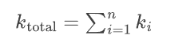
Parallel design is a machine's best friend because redundancy equals added stiffness. You see this everywhere in precision setups: the massive double columns on a gantry mill sharing the vertical load, multiple vibration isolators working together, or the countless parallel cell walls in a honeycomb core.
In real-world structures, engineers must trace the path of the force (identifying the series links) and find the branches (the parallel reinforcements). Synthesizing these paths is the fundamental skill of creating a "Stiffness Budget."
VI. Building Your Design Intuition
Let’s lock in the three most critical takeaways from today:
Intuition 1: You can't change E, but you can weaponize I.
Once you pick a material, its atomic stiffness is set in stone. Your ultimate control knob is the cross-sectional height. Pushing material as far away from the neutral axis as possible is always your top priority.
Intuition 2: Hollow is King.
A hollow shape offers nearly the stiffness of a solid block but at less than half the weight. Closed, hollow sections aren't just a design trend; they are the undisputed "default option" dictated by the laws of structural efficiency.
Intuition 3: Beware the Series Trap.
A single flexible connection in a chain of stiff parts will obliterate all your hard work. Next time (Day 3), we will zoom out from individual components and apply this intuition to the entire machine topology, exploring how the physical path of forces dictates exactly where ultimate precision comes from.
References
[1] Rivin, E. I., Stiffness and Damping in Mechanical Design, Marcel Dekker, 1999, Ch.2 "Stiffness of Structural Components". (Provides a comprehensive analysis of the stiffness of beams, plates, and shell structures, including the specific stiffness advantages of hollow sections.)
[2] Slocum, A. H., Precision Machine Design, Society of Manufacturing Engineers, 1992, §6.3 "Stiffness of Machine Elements". (Offers practical engineering discussions on cross-sectional shape efficiency and structural topology.)
[3] Ashby, M. F., Materials Selection in Mechanical Design, 5th ed., Butterworth-Heinemann, 2017, Ch.3–4. (The classic source for Ashby charts; for the physical relationship between elastic modulus and density, see §3.2.)